Netlists
Netlists are a textual representation of a circuit and used to define circuits for simpliPFy.
A Netlist could look like this
V1 1 0 dc {10}, down
W 1 2, right
R1 2 3 {100}, down
W 3 0; left
In general the structure is like
<componentType><identifier> <positive Node> <negative Node> {<value>}, <drawing hint>
Nodes that have the same identifier/Number are connected.
Component Types
V: Voltage source
I: Current source
R: Resistor
C: Capacitor
L: Inductor
Z: Impedance
W: Wire
Sources
V: Voltage source
I: Current source
A DC source gets the additional parameter dc
<componentType><identifier> <positive Node> <negative Node> dc {<value>}, <drawing hint>
A AC source gets the additional parameter ac, phase and omega_0
<componentType><identifier> <positive Node> <negative Node> ac {<value>} {<phase>} {<omega_0>}, <drawing hint>
for easier use omega_0 can be written as 2*pi*<value in Hz>
<componentType><identifier> <positive Node> <negative Node> ac {<value>} {<phase>} {2*pi*<value in Hz>}, <drawing hint>
e.g.
V1 1 0 ac {10} {0} {100}; up
V1 1 0 ac {10} {0} {2*pi*30}; up
V1 1 0 ac {10} {0} {omega_0}; up
Components R, L, C, Z
A netlist line with R, L, C or Z always contains
<component typy><identifier> <positive Node> <negative Node> {<value>}; <drawing hint>
e.g.
R1 1 2 {1000}; left
the value is encapsulated in {} to ensure that it is parsed correctly there are situations where the brackets can be
ignored, but it is easiest to always use brackets to avoid parsing errors. The pos- and neg node always have to be
an integer. The identifier has to be unique across the components R, L, C, Z because they are transformed internally
into impedances e.g. R1, C2, L3, L4 not R1, C1, L1, L2.
Component W
A netlist line with the component W contains
W<identifier> <start node> <end node>; <drawing hint>
the identifier is optional so it could be
W1 1 2; left
or
W 1 2; left
The length of a wire is always one unit and therefore the same as a Resistor or any other element. If you want to close the circuit the number of wires has to be adjusted to fit the length of elements.
Drawing hints
possible drawing hints are
right
left
up
down
And describe the direction the next component is placed based of the position of the positive node. Drawing hints and Wires can be neglected if you add
# --generalize
at the top of the netlist. Then only describe which components are connected. The generalizeNetlistDrawing package will figure out the lines and positions of the componentes. Won’t work for Wheatstone. For showing the nodes of a circuit you can add
# --shownodes-true
This is helpful for debugging a netlist if it does not look as expected. Each node will be displayed inside the generated svg as a dot with its number beside it.
Circuits that are wider than tall will be displayed “very small” on mobile devices because they are scaled to fit. With
# --optimize-mobile
the circuit is rotated by 90° if it is wider than tall. to make the circuit taller than wide which fits better on mobile devices. For desktops the opposite is true. If a circuit is taller than wide it may be displayed smaller to rotate circuits that are taller than wide by 90° use
# --optimize-desktop
Convert a circuit into a netlist
Start by finding the positive and negative nodes for components. The easiest way is to draw the circuit on paper and then mark the positive and negative point of each component. Enumerate the points. Now you can see the positive and negative nodes for each component.
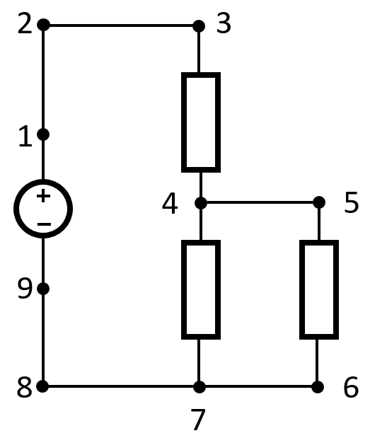
Represented as a netlist the circuit in the picture would be
V1 1 9 dc {10}; up
W 1 2; up
W 2 3; right
R 3 4 {100}; down
R 4 7 {100}; down
W 4 5; right
R 5 6 {100}; down
W 6 7; left
W 7 8; left
W 8 9; up
The values of the components are chosen randomly. The netlist structure is adapted from lcapy, which has great documentation. There are two limitations introduced by our implementation. - no auto naming of components - component values have to be enclosed in {} Examples can be found in Pyodide/Circuits
Magnetic Circuits Netlists
For Magnetic Circuits the netlist syntax defined by lcapy is extended. A magnetic circuit gets a comment at the top to define it as such. The sytnax is not compatible with lcapy and will cause errors if parsed with lcapy:
# --magnetic-circuit
Components in magnetic Netlists:
V: Magnetomotive force source
C: Magnetic Core
G: Magnetic Core with Gap
The structure of a line in a magnetic netlist is
<componentType><identifier> <positive Node> <negative Node> {arg1}, {arg2}, ... ; <drawing hint>
Magnetic Core
Args
{length}, {relative permeability}, {area}
Magnetomotive force source
Args
{length core}, {relative permeability core}, {area core}, {number of windings}, {current of source}
Core With Gap
Args
{length core}, {relative permeability core}, {length gap}, {relative permeability gap}, {area}
length core describes both sides of the core.